
Resolving facility design conflicts between biocontainment & good manufacturing practices for vaccines manufacture
Vaccine Insights 2023; 2(4), 115–125
DOI: 10.18609/vac.2023.022
Many vaccines are manufactured using disease-causing agents or genetically modified organisms. However, many of the standard design principles for vaccines manufacturing facility biocontainment (encompassing biosafety and biosecurity) conflict with design for hygienic operation in good manufacturing practice facilities. This article presents an overview of risk-based approaches to resolve the competing requirements with specific regard to the design of:
- Facility layout, people, material, and waste flows
- Heating, ventilation, and air conditioning
- Construction methodology
- Utility supply
This insight aims to inform those involved in the design of human vaccine production facilities, or contract manufacturing organization selection, where a new organism or platform process is to be introduced. It is a small part of a much wider knowledge area required for ensuring biosafety, and conducting risk assessments when developing, testing, and manufacturing vaccines.
Introduction
Approximately 25% of all new drug approvals are biological products [1]de la Torre BG, Albericio F. The Pharmaceutical Industry in 2021. An Analysis of FDA Drug Approvals from the Perspective of Molecules. Molecules. 2022; 27(3), 1075. , for example, vaccines and blood products. This percentage is likely to increase following the success of vaccines used during the recent COVID-19 pandemic, leading to capability and capacity expansions globally for pandemic preparedness. One thing that these biological products have in common is that they almost all require some form of biological containment and biosecurity during the manufacturing process. This could be due to using a characterized wild-type organism, a genetically modified organism (GMO), or both. Vaccine production often involves the use of a genetically modified host cell line, a live virus seed stock, or cell culture processes that could propagate human pathogens if contaminated during production operations.
Relevant local, national, and international health and safety regulations in relation to the use of chemicals, GMOs, and the handling of biological materials need to be applied when designing and operating vaccine manufacturing facilities and supporting testing laboratories. Table 1 gives an overview of the hazard groups (HG) used in the UK, which relate to the biological containment level (CL) associated with either a pathogen and/or GMO. The term Biosafety Level (BSL) is commonly used in other countries and GMO containment is considered separately, and is sometimes used interchangeably with CL.
| Table 1. Overview of biological hazard groups. | ||
| Biological hazard group | Description | Example organisms/disease |
| 1 | No or low individual and community risk Unlikely to cause human disease | Brewers yeast, E. coli (wild type, non-pathogenic strains) |
| 2 | Moderate individual risk, low community risk Can cause human disease and may be a hazard to employees; it is unlikely to spread to the community and there is usually an effective vaccine or treatment available | Bacillus Pertussis (whooping cough), Legionella spp. |
| 3 | High individual risk, low community risk Can cause severe human disease and may be a serious hazard to employees; it may spread to the community, but there is usually an effective vaccine or treatment available | Bacillus anthracis (anthrax), M. tuberculosis, Rabies virus, Poliovirus |
| 4 | High individual and community risk Causes severe human disease and is a serious hazard to employees; it is likely to spread to the community and there is usually no effective prophylaxis or treatment readily available | Ebola viruses (hemorrhagic fevers) |
Many of the guidelines available have been developed for laboratories rather than manufacturing facilities, and there is little international regulatory harmonization for biorisk management for vaccine manufacturing at production scales (typically greater than 10 L liquid volumes). For UK-based facilities, these include, but are not limited to, those listed in the references section [2]Health and Safety Executive. The large–scale contained use of biological agents. UK HSE. 1998. [3]Health and Safety Executive. The Control of Substances Hazardous to Health Regulations (COSHH). UK HSE. 2002. [4]Health and Safety Executive. The Genetically Modified Organisms (Contained Use) Regulations. UK HSE. 2014. [5]Health and Safety Executive. The Specified Animal Pathogens Order (SAPO). UK HSE. 2008. [6]Health and Safety Executive. The Control of Substances Hazardous to Health Regulations 2002. Approved Code of Practice and Guidance. 6th edition. UK HSE. 2013. [7]Health and Safety Executive. The SACGM Compendium of Guidance: Guidance for The Genetically Modified Organisms (Contained Use) Regulations. UK HSE. 2014. [8]Revised Advice on Laboratory Containment Measures for Work with Tissue Samples in Clinical Cytogenetics Laboratories: Supplement To: ACDP Guidance on Protection Against Blood–borne Infections in the Workplace: HIV and Hepatitis. UK Dept. of Health. 2001. [9]Advisory Committee on Dangerous Pathogens (ACDP). The Management, Design and Operation of Microbiological Containment Laboratories. UK HSE. 2019. [10]Advisory Committee on Dangerous Pathogens (ACDP). Biological agents: The principles, design and operation of containment level 4 facilities. UK HSE. 2006. [11]Advisory Committee on Dangerous Pathogens (ACDP). Managing the risks in laboratories and healthcare premises UK HSE. 2005. [12]Advisory Committee on Dangerous Pathogens (ACDP). Prions and proteopathic seeds: Safe Working and the Prevention of Infection UK HSE. 2021. [13]Advisory Committee on Dangerous Pathogens (ACDP) Approved List of Biological Agents. UK HSE. 2021. [14]Expert Advisory Group on AIDS and the Advisory Group on Hepatitis. Protection against blood–borne infections in the workplace HIV and hepatitis. 1998. [15]EU Directive 2000/54/EC. Biological agents at work. [16]EU Directive 2009/41/EC. Contained use of genetically modified micro-organisms. [17]EN 12128:1999. Biotechnology – Laboratories for research, development and analysis – containment levels of microbiology laboratories, areas of risk, localities and physical safety requirements. [18]EN 12740:1999. Biotechnology – Laboratories for research, development and analysis – Guidance for handling, inactivating and testing of waste.. Subject matter expertise input into structured risk assessments is therefore essential to ensure compliance and biosecurity.
The UK COSHH Regulations [6]Health and Safety Executive. The Control of Substances Hazardous to Health Regulations 2002. Approved Code of Practice and Guidance. 6th edition. UK HSE. 2013. and the revised tables in EU Directive 2000/54/EC [15]EU Directive 2000/54/EC. Biological agents at work. do have separate tables for laboratories and industrial processes, but neither covers the requirements for the safe design and operation of the large scale equipment within the facility. This brings us back again to the importance of structured risk assessments involving the right people who have a working knowledge of how to apply the relevant guidances and regulations.
This is especially relevant for pandemic response, where surge vaccine manufacturing is required, and facilities may need to be repurposed at short notice. The organisms used to make vaccine materials may not be fully characterized at the outset, so a higher containment level may be required until data is obtained.
Although this article refers to more to human vaccines, the same principles apply to veterinary vaccine production facilities. The zoonotic risks of all organisms must be assessed whether for human or animal vaccines. Some countries have separate regulations relating to animal pathogens and those with cross-species risks, for example in the UK there is the Specified Animal Pathogens Order (SAPO) [5]Health and Safety Executive. The Specified Animal Pathogens Order (SAPO). UK HSE. 2008. .
Selected design considerations for biocontainment in a GMP vaccines production facility
Many of the standard GMP design principles for vaccines manufacturing facilities and biosecurity are in conflict. For example, production cleanroom suites are typically positively pressurized to the outside environment, with a net outward flow of air in order to maintain the appropriate hygienic air classification, but a typical laboratory with a pathogen or GMO containment classification is negatively pressurized to the outside environment and/or has a net inwards flow of air (negative to the surrounding areas) to provide the appropriate level of biocontainment.
The following sections discuss the key aspects and propose some design solutions to address these conflicts.
Facility location & layout
Facility location and layout are the first considerations for a GMP vaccine manufacturing facility with a biological containment requirement.
If the facility is in a geologically active area, or in an area prone to extreme weather events or similar, it must be built to withstand those forces. The degree of protection required will depend on a risk assessment of the organisms being handled and whether the requirement is to minimize or prevent release but could include seismic rafts, additional structural reinforcement, building damping, vibration shielding, and the use of earthquake-resistant materials.
If the containment cleanroom is near a road and/or located on an outside wall at ground level, then measures need to be taken to prevent damage from a road traffic accident or a vehicle being forcibly used to enter the cleanroom. Mitigation measures such as the installation of very large bollards, bulletproof glass or metal barred windows, and solid walls, ceiling, and floors (brick, concrete, etc.) on the containment boundary to prevent unauthorized personnel access from inside and outside the facility, are also likely to be required. These have consequences for the facility’s capital cost and operation.
With regards to layout, GMP flows such as the movement of people, waste, and raw materials also need to be examined for biosecurity and GMP compliance. A recent production facility design required the movement of the HG3 inoculum from the working seed bank to the CL3 manufacturing suite. This route used the same corridor as another manufacturing suite and there was no alternative route. The route had to be carefully managed using temporal separation so that there were no other personnel or material movements through the corridor at the same time as the transfer, and decontamination measures were put in place after the transfer before the corridor went back to normal use.
Containment cleanrooms that will involve handling of classified organisms should be located away from other areas, even in their own wing where practical, but this needs to be balanced against the requirements of the process flow. Depending on the risk associated with the organism, it may be appropriate to have a separate entrance and access corridor for those people working in containment cleanrooms, but this requires a greater footprint and is not always practical. Unidirectional flow is an advantage, but is not always possible, especially where the containment cleanroom is part of a retrofit of an existing facility.
When locating a containment cleanroom suite, it is important to always consider the principles of primary and secondary containment. The primary containment barrier is the equipment containing the contaminated material. For open processing, this is the isolator (glove box), or microbiological safety cabinet. For closed processing, it is the pipework, vessels, etc, and the joints between them.
The secondary containment barrier is formed by the architectural and HVAC elements of the room or suite of rooms. A critical and often missed element affecting the building architecture for facilities handling GMOs is the requirement that “the controlled area should be designed to contain spillage of the entire contents of closed system” [4]Health and Safety Executive. The Genetically Modified Organisms (Contained Use) Regulations. UK HSE. 2014. [6]Health and Safety Executive. The Control of Substances Hazardous to Health Regulations 2002. Approved Code of Practice and Guidance. 6th edition. UK HSE. 2013. . Bunding of a large liquid waste inactivation system is relatively simple, but bunding a production suite, where people and materials movement on trolleys is required, takes a bit more creativity. Mobile bunds with sufficient integrity to meet the requirement are often not suitable for GMP operations in terms of materials and cleanability. Built-in elements are preferred, but the materials movement requirements must be carefully assessed, plus this can be more difficult to achieve in a retrofitted facility.
Vaccine facilities typically produce large volumes of contaminated liquid that needs treatment (e.g., inactivation, neutralization, dilution) before it can be safely discharged. The plantroom for the liquid waste inactivation systems should be located as close as possible to the containment cleanrooms. Long gravity drainage pipe runs containing contaminated waste and running outside the containment boundary represent an increased risk of loss of containment. Risk assessments will show what is most appropriate for a specific organism and facility, but wherever possible, best practice is to avoid pipe runs outside the containment area by locating the liquid waste inactivation room directly below the containment cleanrooms it serves. This means that because the secondary containment boundary is continuous, the liquid waste inactivation room can be considered part of the suite.
Heating, ventilation & air conditioning (HVAC)
The flow of air in, out, and around the facility also needs to be considered for biocontainment, so the next most critical aspect of your containment cleanroom is the HVAC system. The pressure cascade between the rooms is one of the primary containment measures and as such it needs to be treated as a
critical system.
A standard pharmaceutical facility HVAC design protects products from external contamination (airborne dust and other contaminants) and internal cross-contamination (other airborne products) as well as protecting the operators from the product. However, these pharmaceutical facility HVAC designs are usually insufficient for a biologics facility handling classified organisms (see Table 1), where, in addition, the operators/environment need to be protected from any potentially hazardous biological agents.
When assessing the HVAC system requirements, it is very important to consider which rooms/suites are served by each air handling unit (AHU) and what impact the failure of an AHU would have on the overall facility pressure cascade, which is essential to maintain the secondary containment barrier.
Case study: HVAC design for a CL3 facility
Below is a review of the HVAC design for a derogated CL3 facility (bloodborne organism not transmissible by airborne routes) with the containment cleanroom at a small positive pressure to atmosphere, but negative to the rest of the facility Figures 1A–C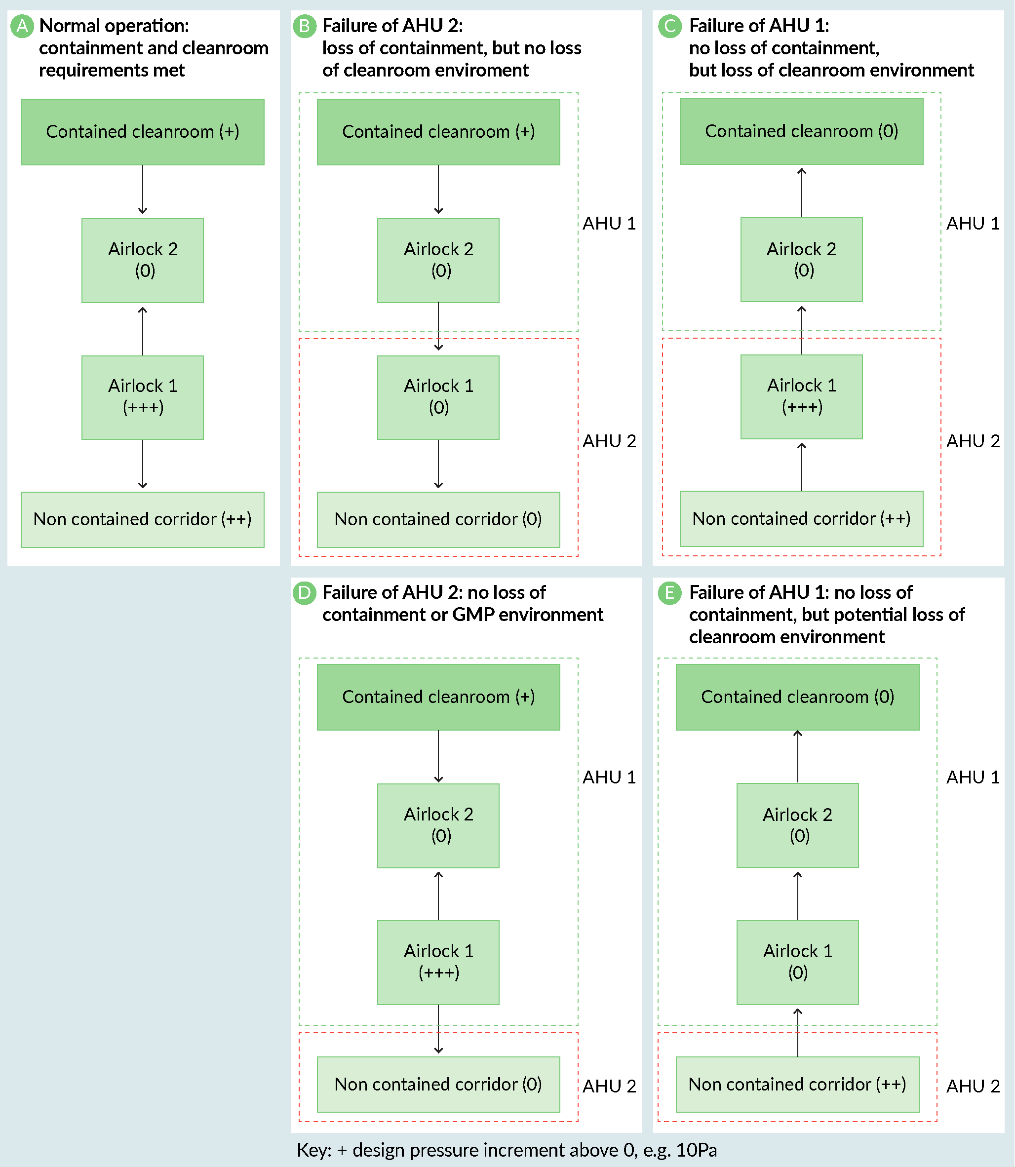 The design of a CL3 facility.). The containment airlocks (Airlock 1) were on the same AHU as the non-contained corridor. This meant that if the corridor AHU (AHU2) had failed, the containment cleanroom would have been positively pressurized to the facility and there would have been a loss of containment. In this case, the problem was easily resolved by moving the containment airlocks (Airlock 1) onto the containment cleanroom AHU (AHU 1) (Figures 1D & E).
Another often overlooked area of HVAC systems is the controlling instrumentation, including proportional damper position feedback. HVAC analogue signals commonly work on the principle of 0–10 V. Therefore, an open circuit failure of 0V would not be detected as an abnormal condition. If signals are specified as 4–20 mA instead, then an open circuit of 0mA can be detected and an alarm raised.
The location of high efficiency particulate air (HEPA) filters is another aspect that is open to debate. For the purposes of biological containment, they are not required until higher containment levels (CL3 or 4) are reached. They can be located inside the room or remotely within the ductwork. It is important to remember that if the HEPA filters are located remotely from the cleanroom, the filters define the containment boundary and therefore the ductwork leading to the filters forms part of the containment boundary. This has implications for the specification of the ductwork. If a containment-classified cleanroom has HEPA filters that are remote from the room boundary, the ductwork up to the filters must be constructed to the same airtightness specification as the containment cleanroom and able to be subjected to the same decontamination measures.
According to current UK regulatory guidance, HEPA filters on the inlet air are not required until CL4. This is based on the principle that the net air flow is inwards and therefore the containment boundary is secure. However, the AHU failure case must be considered. If there is a failure of the containment cleanroom AHU, then there is an airflow path direct to the atmosphere via the inlet air ductwork, resulting in a breach of containment. If an inlet HEPA is not installed, then a gas-tight damper wired to a pressure sensor or some other suitable isolation method should be installed to prevent the loss of containment.
Vaccine manufacturing cleanrooms for aseptic operations will generally have an inlet HEPA filter for GMP purposes. This inlet HEPA can be considered as the containment boundary if it is correctly located; a design strategy that is sufficient for GMP, but not for biocontainment is locating the inlet HEPA for Grade D cleanroom suites close to the AHU, before the ductwork divides to different areas. This means that in the event of an AHU failure, an air path could be present between containment and non-containment areas.
If there are potential bioterrorism risks, multiple small HVAC ducts may be considered to prevent entry by a malicious person crawling through intakes or vents.
Construction methodology
The construction of the containment cleanroom presents a challenge both in terms of specification and constructability. Proprietary cleanroom fabrication systems are usually designed for standard positively pressurized cleanrooms. In a positively pressurized cleanroom, the airtightness of the cleanroom system is important, but not critical, because the air would flow outwards through any small gaps and still maintain the cleanroom environment. Even though the cleanroom panels usually have gaskets in the joints, polymer-based sealant is used to improve cleanability and also improves the airtightness of the cleanroom system. The sealant will degrade over time and outwards air leakage will increase slightly; inspection of all sealed joints should be a routine part of any facility’s planned preventive maintenance program. The HVAC system should therefore be designed with this in mind and have sufficient capacity to increase airflow rates to maintain the pressure cascade between the rooms until maintenance is carried out.
Not all containment cleanrooms will need to meet a specific airtightness standard, but it is important to identify those which do as early as possible so that the details are included in the specifications and checked during construction.
This can be illustrated with an example of a -30Pa, Grade B, CL3 containment cleanroom with a proprietary cleanroom system. As the containment cleanroom is under negative pressure, the engineering team needs to ensure that the cleanroom walling system is physically strong enough to withstand the pressure differential. There have been incidents of panel damage and cleanroom windows getting sucked in during commissioning because the cleanroom system was not specified for vacuum.
The next issue to consider is the airtightness of the cleanroom walling system, not considering any applied sealant. This is important to prevent particulates being sucked into the cleanroom from wall cavities, ceiling voids, etc. The cleanroom system must be specified to achieve a defined airtightness standard and be tested following installation before any sealant is applied to improve cleanability.
Next, we will look at an example of a -30Pa, Grade D, CL3 containment cleanroom constructed using a non-proprietary cleanroom system. Standard building materials, such as plasterboard walls with vinyl, will create the containment barrier. The degree of tolerance of each stage of construction is even more critical. As above, it is important that sealants are not relied upon to achieve the required airtightness. This type of containment cleanroom often causes more issues than those using a cleanroom system. The reason is that standard building tradespeople are used to construct the facility. These contractors are usually not used to building to the tolerances required for this specialist type of work. Unless they are carefully supervised, and the work inspected at every stage, the quality of the construction is unlikely to achieve the required airtightness.
Best practice involves including in the project brief and user requirement specifications that the cleanroom system vendor will build a mock-up for testing prior to committing to the cleanroom system products, then getting the contractor to complete and test one room as a sample before progressing to the other rooms, so that costly mistakes can be avoided.
Utility supply
The supply of GMP utilities into biological containment classified cleanrooms presents some very interesting engineering challenges. The cleanroom construction discussed above is only part of the story. An essential part of most containment cleanrooms is the how utilities are supplied through walls and ceilings. In a standard cleanroom, a hole would be drilled in the cleanroom system, the pipe threaded through, and a trim plate applied and sealed with a polymer-based sealant. For a containment cleanroom, where a high airtightness standard needs to be achieved, this method is not suitable. Proprietary, gasketed, gas-tight, pipework and cable transit systems are available, but their use must be specified early so that the utility pipework and cables can be grouped together to ensure as few penetrations as possible are made in the containment barrier. Penetrations through the containment barrier for other items such as autoclaves, utility panels, pass-through hatches, etc. must also be gasketed and airtight to preserve the integrity of the containment barrier.
Firstly, let us consider a simple dry non-returning service such as clean compressed air, that serves bioreactors, product transfer lines, filter integrity testers, etc. In normal operating conditions, the service will be pressurized. It is therefore safe to assume that containment is maintained by the net inward flow of the gas. The challenge arises when the system depressurizes due to breakdown or maintenance. There is now an open flow path between containment and non-containment areas. In a classical biological containment laboratory this would probably not be an issue because, depending on the containment level, the laboratory is likely to be under a small vacuum or at atmospheric pressure so the flow of air would be inward or neutral. If the HVAC system has been designed to be able to deal with the increased inwards leakage rate, then containment can be maintained. However, with GMP manufacturing we try to avoid having the cleanrooms under vacuum because of the potential to draw particulates from unclassified ceiling voids, wall voids, technical spaces, etc. This means that at CL2, where the requirements are to minimize release, often the cleanroom is positively pressurized to the atmosphere and the containment is managed through strict construction controls to minimize air leakage through the cleanroom wall and ceiling system, and pressure sinks and pressure bubbles in the personnel and materials airlocks and any transfer hatches. It is CL3 containment cleanrooms that are more likely to be under vacuum.
There are several ways of controlling this open-air flow path, which seem obvious until one investigates further. All need careful consideration and risk assessment. For example, if a barrier device such as a filter is fitted in the line, how do you safely manage the decontamination of the pipework downstream of that device following depressurization? When that device needs maintaining or replacing, how do you manage the flow path that is now open again? Probably the most obvious solution is to decontaminate the cleanroom prior to carrying out any maintenance work. This works for planned preventative maintenance, but not in a breakdown scenario. Recovery from a loss-of-containment event is an important consideration that is often overlooked and must be included in the facility design i.e., non-routine operations.
Careful consideration has to be given to the provision of looped services to containment cleanrooms, with a full understanding of the potential risks and characteristics of the organisms being handled. Unlike the example of a dry compressed gas service above, where isolation of different plant areas with valves and/or filters can be achieved, looped utilities such as purified water or water for injection (WFI) often flow through all areas of a manufacturing facility and return to a central tank without any interruption. For a recent vaccine facility project requiring a Grade C cleanroom with a CL3 containment classification, the WFI user point was located outside the containment area in a separate cleanroom and WFI dispensed into single-use bags which were then transported into the containment area. For particularly high-risk applications, where the demand is higher, utilities distribution dedicated to the containment suite may have to be considered.
Translation insight
Biocontainment (biosecurity and biosafety) measures are a key aspect of vaccine manufacturing facility design and operation but are often in conflict with standard GMP design principles for the manufacture of biologics. Maintaining biocontainment is ultimately the responsibility of the vaccine product developer, and loss of containment can have very serious consequences. Like product quality and safety in general, this aspect cannot be compromised on.
In addition, most countries have a list of organisms that they consider represent a risk for bioterrorism. If any of them will be present in the facility, then the relevant government agency will need to be consulted and additional security measures are likely to be needed to prevent theft or unintentional release. Comprehensive guidance for handling of classified organisms at production scales is still to be developed. However, there is a wide range of guidance for handling classified organisms at laboratory scales that can be leveraged.
Non-routine operations need to be considered, as well as operations that may take place in the future. e.g., the introduction of a new manufacturing process into a CMO facility.
Key questions to ask the product and process development teams, facility designers, and/or CMO operations team if you are planning to manufacture a vaccine should include:
- Do the manufacturing processes (all steps including testing and known/likely future activities) involve any classified organisms, i.e., that are biologically hazardous, and/or genetically modified, and/or considered a bioterrorism risk?
- Does the facility location present any abnormal risks for loss of containment, e.g., in an earthquake zone?
- Do the team know which regulations and guidelines (that apply locally, nationally and internationally) need to be complied with?
- Have structured safety risk assessments [19, 20] [adapted from industry guidances on layers of protection analysis (LOPA), bow-tie, failure modes and effects analysis (FMEA), structured what if technique (SWIFT), hazard and operability analysis (HAZOP) etc.] been performed, documented and reviewed for biocontainment, including biosafety and biosecurity, using subject matter experts?
- Do the layout, HVAC design, cleanroom construction system, utilities design, etc. enable the biocontainment needed for (a) routine operations, (b) non-routine operations (e.g., contaminated cell culture disposal, maintenance shutdowns), (c) abnormal situation (e.g., equipment breakdown, integrity failure)?
- For new facilities: Does the cleanroom fabrication team, including sub-contractors, understand the criticality of their work for the manufacture of vaccines/handling of classified organisms? Can they provide mock-ups/samples for testing and inspection?
Finally, a common question that is often asked is if existing facilities can be used for higher containment operations; generally, the answer is no. Vice versa, a high containment facility can be used for less hazardous organism handling, but this is not cost-effective and adds unnecessary operational constraints. As such, facility design needs to be ‘fit for purpose intended’ to address the critical biosafety and biosecurity aspects.
Biographies
Faye Litherland and Ranna Eardley-Patel are both chartered principal process engineers who have designed, commissioned, remediated, validated or operated high-containment facilities used for the manufacture and testing of vaccines and other biologics.
Affiliations
Faye Litherland, CEng, CSci, FIChemE
Director/Principal Consultant
Blue Sky Engineering Ltd
Ranna Eardley-Patel, EngD, CEng, FIChemE
Sustainable Manufacturing Lead, CEPI,
formerly Director/Principal Consultant, PTF UK Ltd
References
1. de la Torre BG, Albericio F. The Pharmaceutical Industry in 2021. An Analysis of FDA Drug Approvals from the Perspective of Molecules. Molecules. 2022; 27(3), 1075. Crossref
2. Health and Safety Executive. The large–scale contained use of biological agents. UK HSE. 1998. Crossref
3. Health and Safety Executive. The Control of Substances Hazardous to Health Regulations (COSHH). UK HSE. 2002. Crossref
4. Health and Safety Executive. The Genetically Modified Organisms (Contained Use) Regulations. UK HSE. 2014. Crossref
5. Health and Safety Executive. The Specified Animal Pathogens Order (SAPO). UK HSE. 2008. Crossref
6. Health and Safety Executive. The Control of Substances Hazardous to Health Regulations 2002. Approved Code of Practice and Guidance. 6th edition. UK HSE. 2013. Crossref
7. Health and Safety Executive. The SACGM Compendium of Guidance: Guidance for The Genetically Modified Organisms (Contained Use) Regulations. UK HSE. 2014. Crossref
8. Revised Advice on Laboratory Containment Measures for Work with Tissue Samples in Clinical Cytogenetics Laboratories: Supplement To: ACDP Guidance on Protection Against Blood–borne Infections in the Workplace: HIV and Hepatitis. UK Dept. of Health. 2001.
9. Advisory Committee on Dangerous Pathogens (ACDP). The Management, Design and Operation of Microbiological Containment Laboratories. UK HSE. 2019.
10. Advisory Committee on Dangerous Pathogens (ACDP). Biological agents: The principles, design and operation of containment level 4 facilities. UK HSE. 2006.
11. Advisory Committee on Dangerous Pathogens (ACDP). Managing the risks in laboratories and healthcare premises UK HSE. 2005.
12. Advisory Committee on Dangerous Pathogens (ACDP). Prions and proteopathic seeds: Safe Working and the Prevention of Infection UK HSE. 2021.
13. Advisory Committee on Dangerous Pathogens (ACDP) Approved List of Biological Agents. UK HSE. 2021.
14. Expert Advisory Group on AIDS and the Advisory Group on Hepatitis. Protection against blood–borne infections in the workplace HIV and hepatitis. 1998.
15. EU Directive 2000/54/EC. Biological agents at work.
16. EU Directive 2009/41/EC. Contained use of genetically modified micro-organisms.
17. EN 12128:1999. Biotechnology – Laboratories for research, development and analysis – containment levels of microbiology laboratories, areas of risk, localities and physical safety requirements.
18. EN 12740:1999. Biotechnology – Laboratories for research, development and analysis – Guidance for handling, inactivating and testing of waste.
19. Risk Assessment for Biological Agents, European Agency for Safety and Health at Work (EU-OSHA). 2010.
20. Burzoni S. Duquenne P. Mater G, Ferrari L. Workplace Biological Risk Assessment: Review of Existing and Description of a Comprehensive Approach. Atmosphere 2020; 11, 741.
Authorship & conflict of interest
Contributions: All named authors take responsibility for the integrity of the work as a whole, and have given their approval for this version to be published.
Acknowledgements: Dedicated to dearly departed mentors and family members, who have supported and enabled us to become engineering subject matter experts.
Disclosure and potential conflicts of interest: The authors have no conflicts of interest.
Funding declaration: The authors received no financial support for the research, authorship and/or publication of this article.
Article & copyright information
Copyright: Published by Vaccine Insights under Creative Commons License Deed CC BY NC ND 4.0 which allows anyone to copy, distribute, and transmit the article provided it is properly attributed in the manner specified below. No commercial use without permission.
Attribution: Copyright © 2023 Blue Sky Engineering Ltd. Published by Vaccine Insights under Creative Commons License Deed CC BY NC ND 4.0.
Article source: Invited; externally peer reviewed.
Submitted for peer review: Mar 21 2023; Revised manuscript received: Apr 20 2023; Publication date: May 3 2023